Frc 2016 Control System
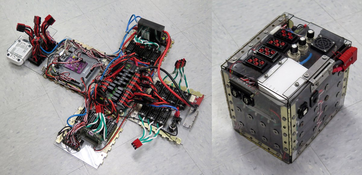
Frc 2016 control system. Locate the following control system components and layout their locations on an appropriate nonconductive surface eg. The FRCsim package is built on top of the Gazebo robotics simulator. Plywood or plastic to permit wiring connections as shown in the power distribution diagram on the FRC Kit of Parts Website.
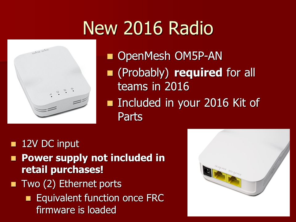
231 Getting Answers To Your Competition Questions. Wiring the 2016 FRC Control System Wiring the 2016 FRC Control System Page 1 OM5P-AN radio with power cable and Ethernet cable Robot Signal Light RSL 4x Victor SP speed controllers 2x PWM y-cables 120A Circuit breaker 4x 40A Circuit breaker 6 AWG Red wire. The Operations Tab is used to control the mode of the robot and provide additional key status indicators while the robot is running.
WPI in conjunction with the Open Source Robotics Foundation has developed a free and open-source 3-D simulation environment available to all FRC teams using C and Java. Ad Entrega mais Rápida da Web. Robot Mode - This section controls the Robot Mode.
That third step tripped us up for a while. Brindes Melhores preços até 70 off e Novidades. The CSA assists teams with Robot Control System-related issues.
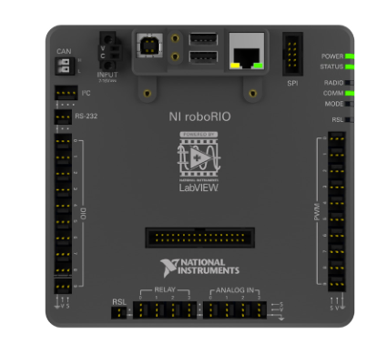
RoboRio Robot Signal Light FRC 2016 Control System OpenMesh OM5P-AN Wireless Bridge Overview plugs into PDP combined C-Rio and DSC two USB ports one Ethernet port CAN port has PWM servo digital IO and analog IO ports plugs into. Configuring a FirstTouch IO Module for FRC. The current control system to be used through the 2014 season is based on Ethernet.
It uses the ADXRS450 Gyroscope and ADXL362 ultra-low power Accelerometer. Light codes on control system components. It may seem odd to find a motor listed here under Control System but thats because this brushless motor comes integrated with a new motor controller.
This is a brushless motor a first for FRC that combines a motor speed controller and tachdirection feedback. The FRC Driver Station and FRC Utilities will always be installed or updated.
It may seem odd to find a motor listed here under Control System but thats because this brushless motor comes integrated with a new motor controller.
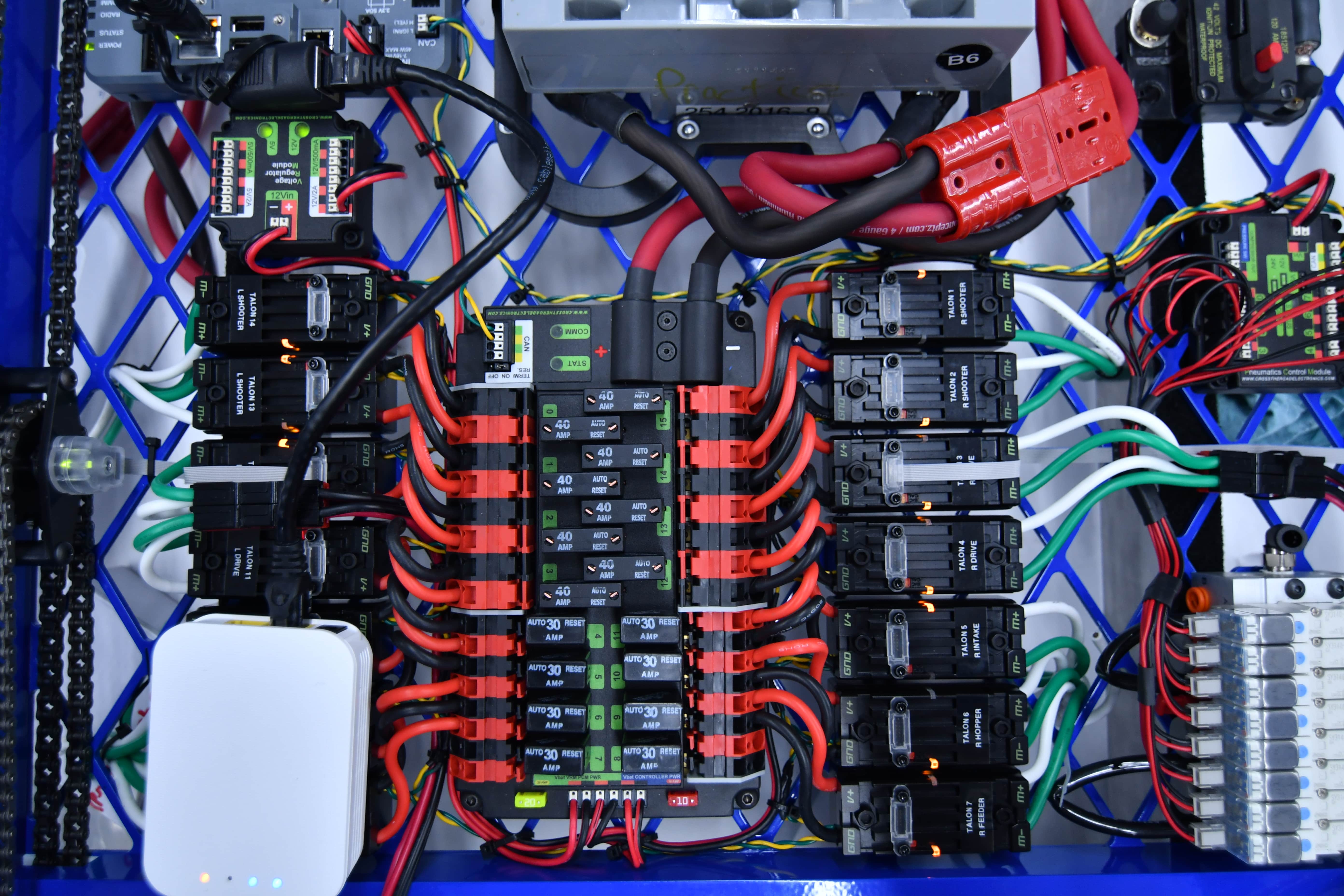
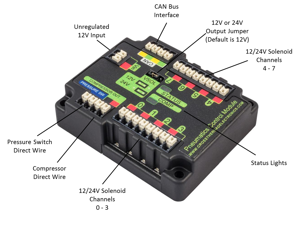
4amp 65amp peak 44watts 2700rpm free speed 45 oz-in peak torque. Wiring the 2016 FRC Control System Wiring the 2016 FRC Control System Page 1 OM5P-AN radio with power cable and Ethernet cable Robot Signal Light RSL 4x Victor SP speed controllers 2x PWM y-cables 120A Circuit breaker 4x 40A Circuit breaker 6 AWG Red wire. Using the ADI FRC GyroXL board 2016 FRC Control System and LabVIEW. Wiring the FRC Control System. FRC Electrical Control System Basics Utah First Robotics Competition. A small list of ones you may have seen includes heaters and air conditioners with thermostats cruise control and the anti-lock braking system ABS on automobiles and fan speed modulation on modern laptops. Disable all networks except for wi-fi when connected to the robot. The goal of this document is to provide a brief overview of the hardware components that make up the FRC Control System. Light codes on control system components.
Installing Electrical Board for RQBS. Using the ADI FRC GyroXL board 2016 FRC Control System and LabVIEW. Each component will contain a brief description of the component function and a link to more documentation. Wiring the FRC Control System. 4amp 65amp peak 44watts 2700rpm free speed 45 oz-in peak torque. Light codes on control system components. 231 Getting Answers To Your Competition Questions.
















Post a Comment for "Frc 2016 Control System"